


TIRA 가진기 시스템
- Head Expander
- Fixture
- 슬립테이블(Slip Table)
- 쿨링시스템(Cooling System)
- 컨트롤러(Remoto Control Unit)
- 파워앰프(Power Amplifiers)
9. 쿨링시스템 (Cooling System) 상위메뉴 > |
|
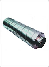
Blowers are used for cooling the shakers. TIRA mainly offers side channel blowers that dispose of an above average cooling performance in comparison with axial blowers. |
9-1. 쿨링시스템(Cooling Blowers)
| Blower | Engine | Dimension | Air Hose | Weight | Soundpressure | |||||
| Designation | Air amount m3/h |
Performance kW | Phase | Voltage V | Frequency Hz | W/H/D (mm) | Diameter (mm) | Length (m) | kg | Level dB(A) |
| TB 0080 | 80 | 0.37 | 1 | 115/230 | 50/60 | 246/247/256 | 40 | 3 | 10 | 53 |
| TB 0140 | 140 | 1.1 | 1 | 115/230 | 50/60 | 286/302/292 | 50 | 3 | 16 | 63 |
| TB 0200 | 210 | 2.2 | 3 | 230/400 | 50 | 334/337/346 | 60 | 5 | 25 | 64 |
| TB 0310 | 315 | 4.0 | 3 | 400 | 50 | 382/384/432 | 60 | 5 | 42 | 69 |
| TB 9 | 870 | 7.0 | 3 | 400 | 50 | 560/605/695 | 100 | 5 | 104 | 86 |
| TB 120 | 1140 | 11.5 | 3 | 400 | 50 | 600/636/701 | 100 | 5 | 131 | 87 |
| TB 8 | 3300 | 5.5 | 3 | 400 | 50 | 841/916/592 | 150 | 5 | 127 | 93 |
| TB 7/FU/11 | 1920 | 11 | 3 | 400 | 50 | 625/700/537 | 150 | 5 | 157 | 102 |
| TB 7/FU/20 | 5820 | 20 | 3 | 400 | 50 | 625/700/575 | 175 | 5 | 157 | 105 |
|
|
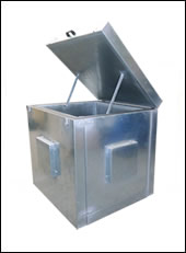
9-2. 쿨링시스템(Acoustic Enclosure & Siliencer)
| Blower | Acoustic Enclosure | Silencer | ||||||
| Designation | Designation | Dimension (LxWxH) mm | Weight | Noise Reduction *dB(A) | Designation | Dimension (LxD) mm | Weight kg | Noise Reduction *dB(A) |
| TB 0800 | TB 0800-AE | 795x699x841 | 45 | 15-23 | TB 0080-SI | 310x65 | 0.2 | 5 |
| TB 0140 | TB 0140-AE | 795x699x841 | 45 | 15-23 | TB 0140-SI | 308x82 | 0.2 | 8 |
| TB 0200 | TB 0200-AE | 795x836x841 | 55 | 15-23 | TB 0200-SI | 308x82 | 0.58 | 6 |
| TB 0310 | TB 0310-AE | 795x836x841 | 55 | 15-23 | TB-0310-SI | 308x82 | 0.58 | 6 |
| TB 9 | TB 9-AE | 1094x1000x1086 | 134 | 5-23 | TB 9-SI | 1012x150 | 1.2 | 3-6 |
| TB 120 | TB 120-AE | 1094x1000x1086 | 134 | 5-23 | TB 120-SE | 1100x160 | 1.2 | 3-6 |
| TB 8 | TB 8-AE | 1094x1179x1271 | 134 | 5-23 | TB 8-SI | 1200x340 | 3.3 | 6-10 |
| TB 7/FU | TB 7/FU-AE | 1130x1630x1630 | 103 | 5-23 | TB 7/FU-SI | 1120x280 | 9.2 | 9-15 |
|
The cooling aggregate includes for the watercooled shakers the complete primary circuit of shaker cooling system and the hydraulics of the shaker's hydrostatic bearings. The unit is designed as a mobile compact device and should be preferably placed next to the amplifier rack. The primary circuit of the cooling unit is for functional reasons based on deionised water. The extraction of the heat capacity is carried out by a secondary process water circuit, which is provided by customer. All necessary elements for energy extraction are involved into the device. In order to achieve a good supervision of circuits there are pressure gauges and flow indicators at many positions available. The device includes an own control circuit based on PLC (programmable logic controller). The control elements and indicators are placed at the front panel. This control works through signal link-ups in cooperation with the superordinated shaker control. |
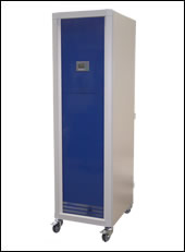
9-3. 쿨링시스템 (Cooling Units)
| C 59410 | C 59430 | |
| Environmental Conditions: | ||
| Temperature | 5 - 30 ° C | 5 - 30 ° C |
| Relative Humidity | 10- 80 % | 10 - 80 % |
| Energy Trnasfex (max.) | 3 KW | 3 KW |
| Process Water: | ||
| Supply temperature | 5 - 15 ° C | 5 - 15° C |
| Volume flow at max. supply temperature | 10 m³/h | 24 m³/h |
| Supply pressure - static | ≤ 8 bar (≤ 800 kPa) | ≤ 10 bar (≤ 1000 kPa) |
| Return - Dynamic differential pressure | ≥ 3 bar (≥ 300 kPa) | ≥ 3 bar (≥ 300 kPa) |
| Dissiplated heat flow (max) | 110 KW | 220 KW |
| Nominal width of supply pipes | 32 mm | 40 mm |
| Connections | R 1 1/4 female | R 1 1/2 FEMALE |
| pH-value | 7 ± 1 | 7 ± 1 |
| Dimensions of dirt particles | < 25 µm | < 25 µm |
| Water hardness (total/carbonate) | < 8° dH | < 8° dH |
| Dimensions (W x H x D) | 600 x 2140 x 970 mm | 800 x 2140 x 1000 mm |
| Weight | 550 kg | 620 kg |
